Why Make a PCB Heater?
Some projects and products will require some kind of heating, whether to prevent electronics from becoming too cold, to help control humidity, to heat up a substance, or even to prevent one material from sticking to another. Most heater elements consist of a high-resistance material that has a voltage applied across it, and the resulting current flow makes the material heat up. For example, nichrome wire (80% nichrome/20% chromium) is commonly used when making heating elements. It has a relatively high resistance (as compared to copper and steel) and forms a chromium oxide layer on the outside after its first use, which prevents the element from deteriorating after further uses. It also has a positive temperature coefficient, which means that as it heats up, the resistance increases, which helps to prevent further heating (i.e., it’s self-regulating). But some applications may not benefit from a nichrome heater element, as such an element typically produces intense heat that radiates from the coil. If such an element were needed to heat a CNC bed uniformly, then it would have to be incredibly long, have many turns, and cover most of the bed area.
So wire heater elements are great for cookers, circuit heaters, and other intense heating applications — but how do we go about making a non-intensive heating element that is easier to make and easier to handle? The answer lies in the faithful PCB trace. With some math and an understanding of material science, we can design our own heater.
A Bit of Material Science
The fundamental principle in any heater element is that components are inherently not 100% efficient, and even the best conductors have some form of resistance. When a voltage is applied across a conductor, a current, I, flows whose value is equal to:
I=VR where R=ρlA
For a conductor with a small resistivity (such as copper) the resulting current will be rather large (assuming a reasonably sized conductor such as a wire). By knowing the current, we can calculate the power dissipated across the wire:
P=VI
So, let us take the example of a 1mm-diameter copper wire whose resistivity is 1.678×10⁻⁸ Ω.m and 10cm in length. The resulting resistance is 0.0021365Ω, and if we apply a voltage of 1V across the wire, the current flowing through the wire would be 468A! Therefore, the power dissipation would be 1V * 468A, which is 468W. This is a massive amount of heat dissipation, and what you must understand is that as the wire gets hot (this would be nearly instant), the resistance also increases, and this reduces the current flow. One good example is the tungsten filament bulb, where the resistance is approximately 132.25 ohms when fully powered (40W bulb at 230V).
You can see that calculating currents and resistance can be rather tricky, but, luckily for us, there are online calculators that can help with designing such elements. One calculator in particular, the PCB trace width calculator, not only helps to calculate trace widths, but also allows us to input a temperature rise. This is crucial, as we can now design an element with a specific temperature rise in mind. So, let’s design a simple seed germination PCB heating element!
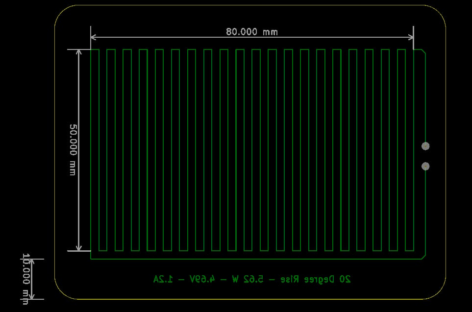
The most important spec in this heater is the temperature rise, as we want to warm the seedlings and not roast them. So, our needed temperature will be a rise of 20 degrees Celsius, and we will run this heater at a current of 1 amp (using nice round figures). We also need to specify a trace length, and this is important because our trace will be the heater itself. For a uniform heat, we need many traces on the PCB, so choosing a large value helps here. In this case, I will enter 2 meters. The result from the calculator tells us that a trace width of 7 mil will produce the needed heat rise if a voltage of 10V is applied across it. However, 7 mil on a CNC is very tricky, so I will adjust the current setting until the trace width is at least 10 mil. Adjusting the current to 1.2 amps results in a trace width of 10 mil with a voltage drop of 4.69 volts. This is more practical for construction at home, and with our newfound details, we can get to work on PCB layout.
Trace Layout
We have a trace length of 2 meters and a trace width of 10 mil (0.254mm). We need to create this trace and meander it onto a PCB. It is as this point that we have to decide a trace separation and heater dimension. The two are inversely proportional, which means that if the heater itself is increased in size, then the trace separation will increase, which will reduce the heating uniformity. For our example, we will make a rather small heater of 5cm wide with a 1cm border. This means that each trace going back and forth will be 5cm in length. For 2m of trace, this results in 40 traces. If we choose a trace separation of 2mm, then the resulting heater will be 8cm long.
If we increase the length of the trace in this design, then the voltage needed to produce the same temperature rise would increase. Keep this in mind if the resulting heater is too small. Now that you have the science, math, and online calculators at your disposal, you can design your own PCB heater!
Various Designs
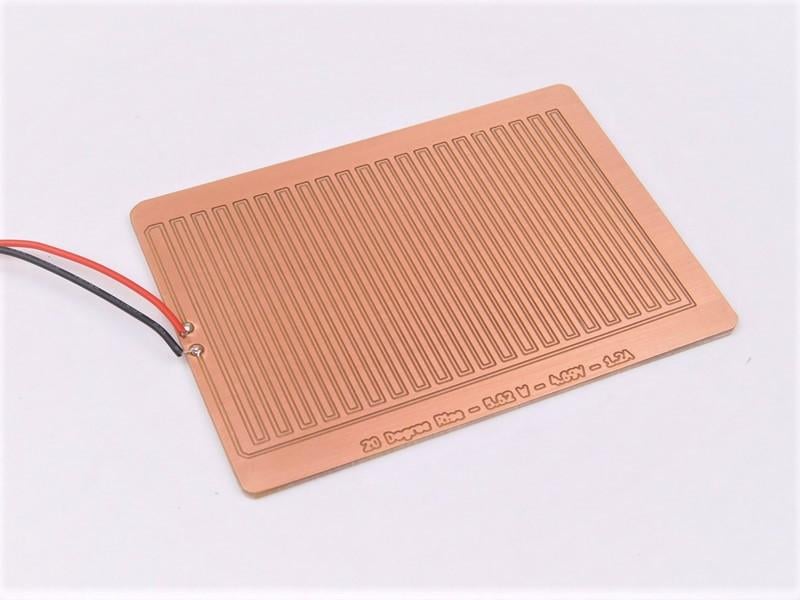
Since the temperature rise in a heater is a function of its resistance and voltage, you don’t always need to design a heater from scratch. So long as you can apply a specific voltage, you should be able to achieve your desired temperature with any heater. The size of the heater is probably the most important characteristic, so attached to this project are various heater elements (including their design files).