This simple weather station can be used to track and predict short-term weather.
Knowing what the weather will do before it happens is a mammoth task and requires supercomputers to perform billions of calculations. However, short term weather is easier to predict and in this DIY hacking project, we will build a simple weather station that can be used to track and predict the weather.
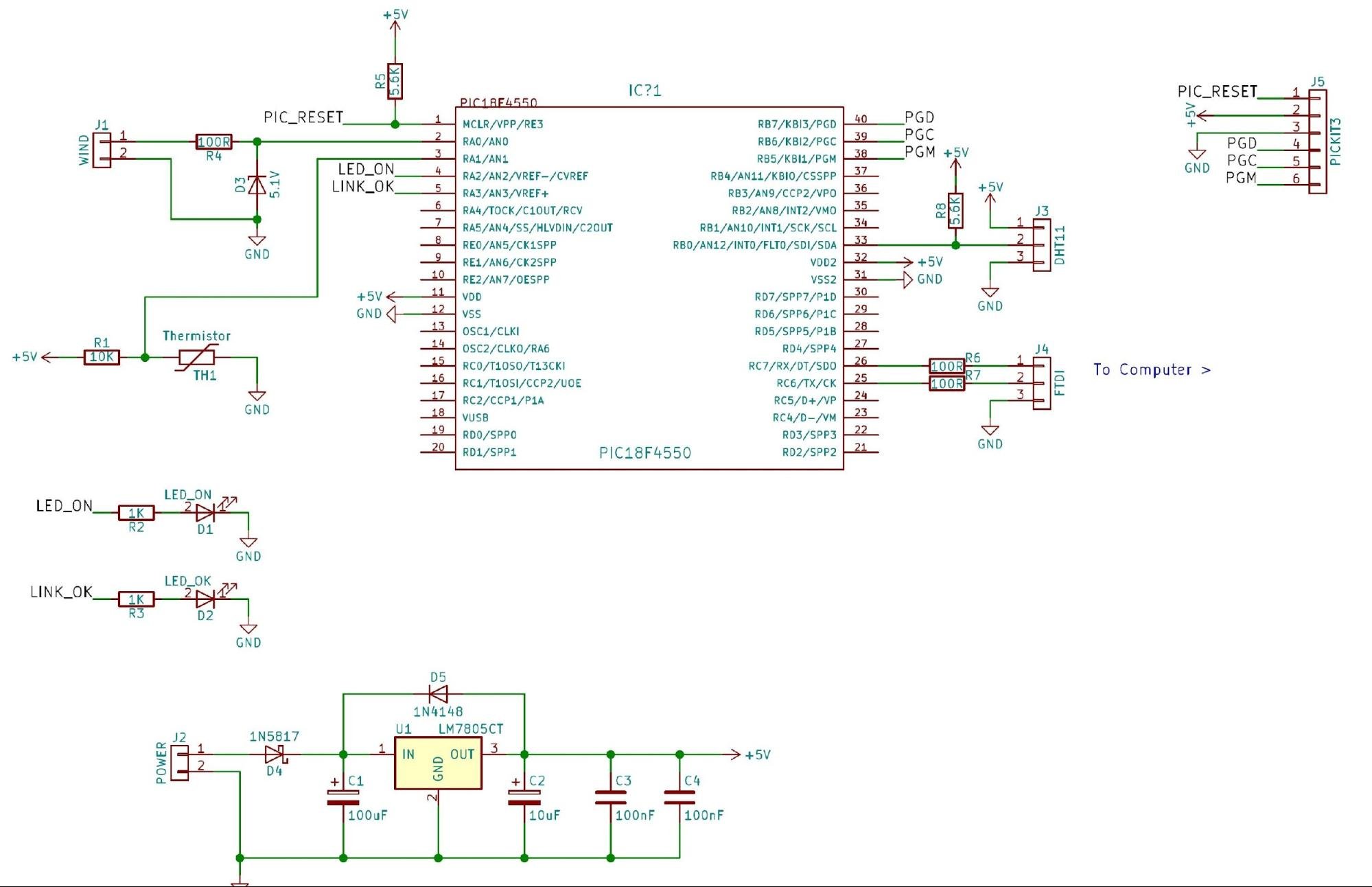
Schematic
How Does the Weather Station Work?
The circuit itself is not new or unique; it is a basic microcontroller circuit with sensor inputs and power control. The power control is based around a 7805 linear regulator that will produce a steady 5V for the microcontroller. The regulator also has two protection diodes; D4 which is for input polarity protection and D5 which prevents voltage spikes on the microcontroller side from damaging the regulator.
The FTDI port has two 100 ohm resistors in series with the data lines to protect both the FTDI and microcontroller from voltage spikes from either side. The DHT11 data line has a 5.6K pull-up resistor as it is an open drain circuit where either the microcontroller or DHT11 can pull the line down to ground.
The anemometer input comes from a small DIY anemometer made from a DC motor and a few small cups. As the motor spins, a small voltage is generated across the motor and this is voltage is sent to the microcontroller via an analog input. As the wind speed increases, the anemometer spins faster which results in a larger voltage. Therefore, the voltage read from the anemometer directly corresponds to wind speed. This input is protected with the use of D3, which is a Zener diode and this serves two purposes; it removes negative voltages that may form and also clips the input as to prevent the analog voltage from damaging the microcontroller pin.
The DHT11 can only go down to 0 degrees, so a thermistor is also included on the PCB. This thermistor is in parallel with a resistor (which must be selected carefully) so that the temperature of the air directly corresponds to a voltage. This voltage is read in through another analog pin and thus allows the microcontroller to make temperature readings from a thermistor instead of the DHT11. The rest of the circuitry is either for power control or protection and is not too important in the design's function. The rest of the magic happens in the code for the microcontroller which can be found attached to this project. While the explanation of the code would be tedious, a quick description will be given. The code sits in an infinite loop, taking readings from the various devices. Upon each loop (which include long delays), the microcontroller will stream the recorded values over UART to a serial device of your choice. Therefore, to maximize use of this project, a visual basic project can be made that takes readings from the serial port and then either log them to a file or display them on several graphs. From there, the gathered data could be matched against the current weather and it won't be long before your weather stations data can be used to try and predict the weather.
Construction
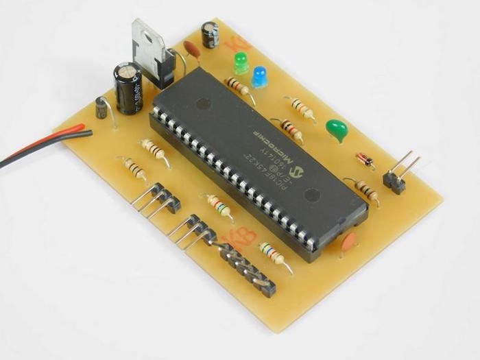
This project consists of two main parts for the weather station itself and a third optional project to make the weather station more useable. The first step is to build the circuit shown in the schematic. This can be done with most circuit construction techniques including breadboard, stripboard, and PCBs. For this project, I used a PCB milled on a CNC for convenience as well as a more professional look. All the CNC files can be found in the project folder and include all the needed G-Code for a CNC 3020 (also included is auto leveled code).
Once the circuit has been built, the anemometer needs to be made. This was done using a small motor, a few plastic cups, and other generic materials such as wood and bamboo skewers. The idea is for the motor to spin when the wind blows so a voltage is generated at its terminals. But before connecting the anemometer, find out which motor terminal is positive during windy conditions, otherwise, a negative voltage will be generated and this will not be recognized by the microcontroller. With the anemometer built, connect it to a long pole and have it upright and connect the anemometer to the circuit.
For more instructions on building an anemometer, check out this tutorial: Measuring Wind Speed with a DIY Anemometer.
The third stage is optional; to code a weather station using your preferred language. While many languages and environments exist, I personally advise visual basic (especially when working with serial ports). In less than 10 minutes, you can have a Windows GUI program recording data over the FTDI serial port connection and have it displayed on a graph. What you do with the data is up to you however one idea would be to gather data and match up the current weather. From there, you may be able to predict the weather and have your very own weather station!