Make a clap-activated mains device to automate your home.
Home automation is still in its infancy. While there are some clever devices that can control your lights and curtains, the majority of people still prefer the old-fashioned do-it-yourself method. But it won’t be long before home automation takes over, so in this project, we will build a clap-activated mains device!
Warning: This device deals with mains electricity and is shown as a demonstration only. Those who wish to attempt a project involving mains should be certified to do so and understand the dangers of working with high voltages.
Schematic
How Does the Clap-Activated Mains Device Work?
The circuit's function is to take a loud sound and then turn on or off a mains device. The first part of the circuit is an electret microphone that converts sound waves into voltages. This voltage is then coupled to remove the large DC offset produced by the 10k pull-up resistor. The signal is then smoothed via R3 and C2 to turn the many peaks of a clap into a smoother pulse, and this smoother signal is then fed into an op-amp in a comparator configuration. The output of the comparator is then connected to a Schmitt trigger, whose parameters are adjustable thanks to RV2 and RV1. The output is then used to toggle a 4013 flip-flop that is configured as a toggle by connecting the inverting output to the data input. This results in an output that toggles every time a loud noise is detected (e.g., from a clap).
The 4013 is used to control the state of a relay that is used to turn on and off our mains supply to our mains connected device. It is imperative that the live (sometimes called "hot") wire is switched and the neutral and earth lines left connected. Such switching is important, because disconnection of the neutral and earth connections can potentially leave to a circuit that will not disconnect under fault conditions (a feature found in the circuit breaker box in your home).
The circuit demonstrated here works well with the electret microphones stocked in my workshop, but if you find that the signal from your microphone is too small, an additional amplifier can be included between C2 and the comparator to produce a larger output.
Read More
Construction
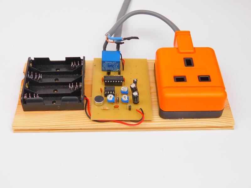
The circuit itself can be constructed using many techniques including PCBs, stripboard, and breadboard. However, the relay itself should only be near the control circuit if it is on a PCB and has suitable traces for handling mains voltage. If any other method than a PCB is to be used, exercise extreme caution. The control relay should not have any contacts exposed, and all mains electricity parts should be located in an insulating, approved box (many project boxes work well for this). The example shown here is not how the project should be completed, but is meant to demonstrate the various parts carefully. Despite not being in a safe enclosure, the demonstrated project shows a dedicated socket outlet and plug inlet that connects to the mains. Connections to this project should never be done with wiring directly taking a feed from the house wiring (they should use appropriate plugs into sockets).
The demonstrated projects